Chuan's Notes
I take notes here about the problems I solved !
Java
reduce in Java
The reduce function below will just work fine.
Integer sum = integers.reduce(0, (a, b) -> a+b);
However, when the arguments paassed to the BinaryOperator<T> accumulator are of different types, the compiler complains.
Example
Given a list of bank transactions.
public class Transaction {
  double amount;
}
We want to calcuate the sum
List<Transaction> transactions; //...

double sum = transactions.stream()
    .reduce(0.0, (result, t) -> result + t.getAmount(), Double::sum);
We have to provide a Double::sum combiner parameter for it to compile. Taking a closer look at the API:
<U> U reduce(U identity,
             BiFunction<U,? super T,U> accumulator,
             BinaryOperator<U> combiner)
The arguments of our accumulator above has different types which are of Transaction and Double. Therefore, we need the third combiner.
foldLeft in Java
In Java, you can use the Collector interface to perform reduction operations on a collection, which is similar to the foldLeft function in Scala.
static <T,R> Collector<T,R,R> of(Supplier<R> supplier,
                                 BiConsumer<R,T> accumulator,
                                 BinaryOperator<R> combiner,
                                 Collector.Characteristics... characteristics)
Example
Given an example that one customer has multiple bank accounts:
public class BankAccount {
    String customerName;
    double balance;

    // getter, setters..
}
We want to group a list of bank accounts by customer name and find out the balance across the customers' bank accoutns.
List<BankAccount> bankAccounts; //...

Map<String, Double> customers = bankAccounts.stream()
    .collect(Collector.of(
        (Supplier<HashMap<String, Double>>) HashMap::new,
        (result, bankAccount) -> {
            var sum = result.getOrDefault(bankAccount.getCustomerName(), 0.0);
            result.put(b.getCustomerName(), sum + bankAccount.getBalance());
        },
        (a, b) -> a
    ));
This can also be addressed by using Java built-in groupingBy collector:
bankAccounts.stream()
    .collect(Collectors.groupingBy(BankAccount::getCustomerName,
        Collectors.summingDouble(BankAccount::getBalance)));
Spring Actuator
Spring Actuator enables many production-ready features for your Spring Boot Applications such as health checks, metrics gathering.
<dependencies>
    <dependency>
        <groupId>org.springframework.boot</groupId>
        <artifactId>spring-boot-starter-actuator</artifactId>
    </dependency>
</dependencies>
Health Checks
When deploying applications to a kubenetes cluster, it is ofter necessary to configure Liveness, Readiness probes.
The differences between liveness probs and readiness probes are, as follows:
- The kubelet uses liveness probes to know when to restart a container.
- The kubelet uses readiness probes to determine when a container is ready to start accepting traffic.
Spring Actuator exposes both liveness and readiness check endpoints. However, it is important to undertand what to be included in which health group - liveness or readiness.
Considering an Spring Boot application that connects to a Postgres or MySQL database, if the database itself is in outage, restarting the application will not solve the database issues. Therefore, the database health check should not be included in the liveness group. Rather, we want to prevent the container from accepting traffics by including the databae health check in the readiness group.
management.server.port=9000
management.endpoints.web.exposure.include=info,health
management.endpoint.health.enabled=true
management.endpoint.health.show-details=always
management.endpoint.health.probes.enabled=true
management.endpoint.health.group.readiness.include=readinessState,db
The readinessState is what Spring Boot use to represent whether the application is ready to accept traffic or not. Similaly, the livenessState represents the liveness of the application and the correctness ofits internal state.
Therefore, the container readiness to accept traffics is dependent on both the application internal state and the database status.
To check the application readiness, you can go to localhost:9000/actuator/health/readiness, which is also what you should configure in the kubenetes readiness probs.
livenessProbe:
  httpGet:
    path: /actuator/health/liveness
    scheme: HTTP
    port: 9000
  initialDelaySeconds: 45
  timeoutSeconds: 40
readinessProbe:
  httpGet:
    path: /actuator/health/readiness
    scheme: HTTP
    port: 9000
  initialDelaySeconds: 60
  timeoutSeconds: 10
Custom Health Checks
To implement custom health checks, you can extend the Spring AbstractHealthIndicator class.
However, for applications that use non-blocking clients, for intance, Lettuce for Redis. You need to instead extend the Spring AbstractReactiveHealthIndicator.
import io.lettuce.core.RedisConnectionException;
import io.lettuce.core.api.StatefulRedisConnection;
import org.springframework.boot.actuate.health.AbstractReactiveHealthIndicator;
import org.springframework.boot.actuate.health.Health;
import org.springframework.boot.actuate.health.Health.Builder;
import org.springframework.context.annotation.Configuration;
import reactor.core.publisher.Mono;

import java.io.IOException;
import java.io.StringReader;
import java.util.Properties;

@Configuration(proxyBeanMethods = false)
public class RedisHealthIndicator extends AbstractReactiveHealthIndicator {

  private final StatefulRedisConnection<String, String> connection;

  public RedisHealthIndicator(StatefulRedisConnection<String, String> connection) {
    super("Redis health check failed");
    this.connection = connection;
  }

  @Override
  protected Mono<Health> doHealthCheck(Builder builder) {

    if (!connection.isOpen()) {
      return Mono.just(this.down(builder, new RedisConnectionException("unable to connect")));
    }

    return connection.reactive().info("server")
        .map(info -> {
          final Properties p = new Properties();
          try {
            p.load(new StringReader(info));
          } catch (IOException e) {
            LOG.warn("failed to load redis server properties", e);
          }
          return this.up(builder, p);
        })
        .onErrorResume(throwable -> Mono.just(this.down(builder, throwable)));
  }

  private Health up(Builder builder, Properties info) {
    return builder.up().withDetail("server", info).build();
  }

  private Health down(Builder builder, Throwable cause) {
    return builder.down(cause).build();
  }
After having created the custom health indicator, you need to add it to the health group:
management.endpoint.health.group.readiness.include=readinessState,redis,db
Note that the naming needs to correspond to the class name. For example, if you have PubsubHealthUbducator.java, then you need to have include=pubsub in the actuator configuration. If you have PubSubHealthIndicator.java, then you need to have camel case include=pubSub.
Swagger
We often use Swagger to generate REST API documentations and even REST client. However, if put all the API definition in a single Swagger .yaml file, it gets really messy as the application grows.
To have a clean Swagger configuration, first create a multiple module maven project, as follows:
project
  - rest-api
    - v1
      common.yaml
      pet.yaml
      pet-img.yaml
      store.yaml
      user.yaml
      petstore-api.yaml
    pom.xml
  - rest-client
    - v1
    pom.xml
  pom.xml
- The
rest-apimodule will be used on the server side to implement the generated REST interfaces. - The
rest-clientmodule can be used in component tests or other services integrating with your service.
REST API generation
In the petstore-api.yaml file, we specify the service resources as:
openapi: '3.0.0'
info:
  title: Pet Store API
  description: Pet store
  version: '0.1'
  termsOfService: url

paths:
  /pet/{petId}
    $ref: 'pet.yaml#/api'
  /pet/{petId}/images
    $ref: 'pet-img.yaml#/api'
  /store/{storeId}
    $ref: 'store.yaml#/api'
  /user/{username}
    $ref: 'user.yaml#/api'
We then specify the API details of the sub-resouces in each swagger yaml file, for example pet.yaml:
openapi: '3.0.0'

api:
  put:
    tags:
      - Pet
    summary: Create Pets
    operationId: createPet
    parameters:
      - $ref: 'common.yaml#/components/parameters/petId'
    requestBody:
      required: true
      description: OK
      content:
        application/json:
          schema:
            $ref: '#/components/schemas/UpdatePetRequest'
    responses:
      '200':
        description: OK
        content:
          application/json:
            schema:
              $ref: '#/components/schemas/UpdatePetResponse'
      '404':
        $ref: 'common.yaml#/components/schemas/BadRequest'
  delete:
    # .....

components:
  schemas:
    UpdatePetRequest:
      type: object
      properties:
        name:
          type: string
        category:
          $ref: '#/components/schemas/PetType'
    UpdatePetResponse:
      # ....
    PetType:
      type: string
      enum:
        - DOG
        - CAT
You can put the common models to a common.yaml file and reference it using $ref: 'common.yaml#/'.
openapi: '3.0.0'
components:
  parameters:
    petId:
      in: path
      name: petId
      required: true
      schema:
        type: string
  responses:
    BadRequest:
      description: Invalid Parameters
      content:
         application/json
           schema:
            $ref: '#/components/schemas/Error'
  schemas:
    Error:
      type: object
      properties:
        code:
          type: string
        message:
          type: string
      required:
         - code
         - message
We now have a way to seperate sub-resourcs definitions into different yaml files. Next is to add the Swagger Codegen maven plugin to generate the Java models and interfaces.
In the project root pom.xml, add the following dependencies. We exclude some dependencies from io.swagger.codegen.v3 since they are not needed and also cause some Sonarcube vulneribilites.
<dependencyManagement>
	<dependencies>
	  <dependency>
	    <groupId>io.swagger.codegen.v3</groupId>
	    <artifactId>swagger-codegen-maven-plugin</artifactId>
	    <version>3.0.27</version>
	    <exclusions>
	      <exclusion>
		<groupId>org.apache.maven</groupId>
		<artifactId>maven-core</artifactId>
	      </exclusion>
	      <exclusion>
		<groupId>io.swagger.codegen.v3</groupId>
		<artifactId>swagger-codegen-generators</artifactId>
	      </exclusion>
	      <exclusion>
		<groupId>io.swagger</groupId>
		<artifactId>*</artifactId>
	      </exclusion>
	      <exclusion>
		<groupId>commons-io</groupId>
		<artifactId>commons-io</artifactId>
	      </exclusion>
	    </exclusions>
	  </dependency>
	  <dependency>
	    <groupId>org.springframework.boot</groupId>
	    <artifactId>spring-boot-starter-web</artifactId>
	    <version>2.5.2</version>
	    <scope>provided</scope>
	  </dependency>
	</dependencies>
</dependencyManagement>
Then in the rest-api/pom.xml, we have the following:
<dependencies>
	<dependency>
	    <groupId>io.swagger.codegen.v3</groupId>
	    <artifactId>swagger-codegen-maven-plugin</artifactId>
	</dependency>
	<dependency>
	    <groupId>org.springframework.boot</groupId>
	    <artifactId>spring-boot-starter-web</artifactId>
	</dependency>
</dependencies>

<build>
	<plugins>
	    <plugin>
		<groupId>io.swagger.codegen.v3</groupId>
		<artifactId>swagger-codegen-maven-plugin</artifactId>
		<version>3.0.27</version>
		<executions>
		    <execution>
			<id>generate-petstore-api</id>
			<goals>
			    <goal>generate</goal>
			</goals>
			<configuration>
			    <inputSpec>${project.basedir}/v1/petstore-api.yaml</inputSpec>
			    <language>spring</language>
			    <generateApiTests>false</generateApiTests>
			    <generateModelTests>false</generateModelTests>
			    <configOptions>
				<apiPackage>se.petstore.generated.api.rest</apiPackage>
				<modelPackage>se.petstore.generated.api.rest.model</modelPackage>
				<dateLibrary>java8</dateLibrary>
				<async>true</async>
				<java8>true</java8>
				<library>spring-boot</library>
				<useTags>true</useTags>
				<interfaceOnly>true</interfaceOnly>
			    </configOptions>
			</configuration>
		    </execution>
		</executions>
	    </plugin>
	</plugins>
</build>
REST Client generation
To generate REST client, add the following to rest-client/pom.xml file.
<dependencies>
	<dependency>
	    <groupId>se.petstore</groupId>
	    <artifactId>se.petstore.rest-api</artifactId>
	    <version>${project.version}</version>
	</dependency>
</dependencies>
<build>
	<plugins>
	    <plugin>
		<groupId>io.swagger.codegen.v3</groupId>
		<artifactId>swagger-codegen-maven-plugin</artifactId>
		<version>3.0.27</version>
		<executions>
		    <execution>
			<id>generate-petstore-client</id>
			<goals>
			    <goal>generate</goal>
			</goals>
			<configuration>
			    <inputSpec>${project.parent.basedir}/rest-api/v1/petstore-api.yaml</inputSpec>
			    <language>java</language>
			    <generateApis>true</generateApis>
			    <generateModels>false</generateModels>
			    <generateApiTests>false</generateApiTests>
			    <generateModelTests>false</generateModelTests>
			    <configOptions>
				<invokerPackage>se.petstore.generated.api.rest.client</invokerPackage>
				<apiPackage>se.petstore.generated.api.rest.client</apiPackage>
				<modelPackage>se.petstore.generated.api.rest.model</modelPackage>
				<dateLibrary>java11</dateLibrary>
				<library>resttemplate</library>
				<useTags>true</useTags>
			    </configOptions>
			</configuration>
		    </execution>
		</executions>
	    </plugin>
	</plugins>
</build>
Swagger UI
In the server application, add the SpringFox dependency:
<dependency>
	<groupId>io.springfox</groupId>
	<artifactId>springfox-boot-starter</artifactId>
	<version>3.0.0</version>
</dependency>
Then define the Docket Bean. The following configuration requires a Bearer token when makeing the API calls.
import org.springframework.beans.factory.annotation.Value;
import org.springframework.context.annotation.Bean;
import org.springframework.context.annotation.Configuration;
import org.springframework.web.bind.annotation.RestController;
import springfox.documentation.builders.PathSelectors;
import springfox.documentation.builders.RequestHandlerSelectors;
import springfox.documentation.service.ApiKey;
import springfox.documentation.service.AuthorizationScope;
import springfox.documentation.service.SecurityReference;
import springfox.documentation.spi.DocumentationType;
import springfox.documentation.spi.service.contexts.SecurityContext;
import springfox.documentation.spring.web.plugins.Docket;

import java.util.Collections;

@Configuration
class AppConfig {

  @Bean
  public Docket api() {
    AuthorizationScope[] authScopes = new AuthorizationScope[]{
      new AuthorizationScope("global", "accessEverything")
    };
    SecurityReference securityReference = new SecurityReference("Bearer", authScopes);
    SecurityContext securityContext = SecurityContext.builder()
        .securityReferences(Collections.singletonList(securityReference))
        .build();

    return new Docket(DocumentationType.SWAGGER_2)
        .select()
        .apis(RequestHandlerSelectors.withClassAnnotation(RestController.class))
        .paths(PathSelectors.any())
        .build()
        .securitySchemes(Collections.singletonList(new ApiKey("Bearer", "Authorization", "header")))
        .securityContexts(Collections.singletonList(securityContext));
  }
}
Create a Maven Plugin with FreeMarker
Sometimes it is quite convinent to generate Java source code from a specification, such as from a .yaml file.
You can create a maven plugin to read the .yaml specification and generate the Java source code into the target/generated-sources/ directory using FreeMarker, a Java Template Engine.
To create a maven plugin with freemarker, you need the following dependencies. And you will typically name your plugin <yourplugin>-maven-plugin.
  <dependencies>
    <dependency>
      <groupId>org.apache.maven</groupId>
      <artifactId>maven-plugin-api</artifactId>
      <version>3.6.3</version>
    </dependency>
    <dependency>
      <groupId>org.apache.maven.plugin-tools</groupId>
      <artifactId>maven-plugin-annotations</artifactId>
      <version>3.6.0</version>
      <scope>provided</scope>
    </dependency>
    <dependency>
      <groupId>org.apache.maven</groupId>
      <artifactId>maven-project</artifactId>
      <version>2.2.1</version>
    </dependency>
    <dependency>
      <groupId>org.freemarker</groupId>
      <artifactId>freemarker</artifactId>
      <version>2.3.30</version>
    </dependency>
  </dependencies>
As an example, we are going to create a maven plugin named client-notification-maven-plugin which reads a YAML specification and generates Java source code.
Mojo
To create the plugin, we need to first create a Java mojo class representing the plugin's goals generate.
@Mojo(name = "generate", defaultPhase = LifecyclePhase.GENERATE_SOURCES)
public class ClientNotificationMojo extends AbstractMojo {
}
To use the plugin in other Java projects, we need to specify the corresponding goal generate , as follows
<build>
  <plugins>
    <plugin>
      <groupId>com.lakritsoft</groupId>
      <artifactId>client-notification-maven-plugin</artifactId>
      <executions>
        <execution>
          <goals>
            <goal>generate</goal>
          </goals>
        </execution>
      </executions>
    </plugin>
  </plugins>
</build>
Package of generated source code
When generating the Java source code, it is often desired to specify the Java package.
Assume the project has the groupId and artifactId below:
<groupId>com.lakritsoft.myservice</groupId>
<artifactId>app</artifactId>
And we want the generated the souce code to be located at com.lakritsoft.myservice.clientnotification package.
app/
  target/
    generated-sources/
      client-notification/
	java/
          com.lakritsoft.myservice.clientnotification // package name
  pom.xml
pom.xml
To find out the project groupId and specify the source package:
@Mojo(name = "generate", defaultPhase = LifecyclePhase.GENERATE_SOURCES)
public class ClientNotificationMojo extends AbstractMojo {

  @Parameter(defaultValue = "target/generated-sources/client-notification/java")
  private File outputDirectory;

  @Parameter(
      defaultValue = "${project}",
      required = true,
      readonly = true)
  private MavenProject project

  @Override
  public void execute() throws MojoExecutionException, MojoFailureException {
    String srcPackage = project.getGroupId() + "." + "clientnotification";
    File srcDir = new File(outputDirectory, srcPackage.replace(".", "/"));

    srcDir.mkdirs();

    project.addCompileSourceRoot(outputDirectory.getAbsolutePath());
  }
}
Read the YAML specification from the Java Mojo Class
If the YAML specifications is published to Maven artifact repository, such as Nexus, as zip format, we can use maven-dependecy-plugin to unpack the zip file.
 <build>
    <plugins>
      <plugin>
        <groupId>org.apache.maven.plugins</groupId>
        <artifactId>maven-plugin-plugin</artifactId>
        <version>3.6.0</version>
      </plugin>
      <plugin>
        <groupId>org.apache.maven.plugins</groupId>
        <artifactId>maven-dependency-plugin</artifactId>
        <executions>
          <execution>
            <id>unpack-yaml-specification</id>
            <goals>
              <goal>unpack</goal>
            </goals>
            <phase>compile</phase>
            <configuration>
              <artifactItems>
                <artifactItem>
                  <groupId>com.example</groupId>
                  <artifactId>yaml-specification</artifactId>
                  <version>${version}</version>
                  <type>zip</type>
                  <outputDirectory>${project.build.directory}/classes/specs</outputDirectory>
                  <includes>specification.yaml</includes>
                </artifactItem>
              </artifactItems>
            </configuration>
          </execution>
        </executions>
      </plugin>
    </plugins>
  </build>
With maven-dependency-plugin, We unpack the YAML files into the project classpath - app/target/classes/specs.
And to read the YAML file, we can ues Java ClassLoader:
@Mojo(name = "generate", defaultPhase = LifecyclePhase.GENERATE_SOURCES)
public class ClientNotificationMojo extends AbstractMojo {

  @Override
  public void execute() throws MojoExecutionException, MojoFailureException {

     InputStream is =
        this.getClass().getClassLoader().getResourceAsStream("specs/specification.yaml");

  }
}
FreeMarker
We have now covered how to create the src package for the generated clasess, and how to read YAML files. Next step is to generate the Java source files using FreeMaker template engine.
We create the template files and put them inside the resources directory:
client-notification-maven-plugin
  src/
    main/
      java/
      resources/
        tempaltes/
          ExampleJava.ftlh
The content of the ExampleJava.ftlh is as follows:
package ${package};

public class ExampleJava {

}
Then in our Java Mojo class, we can process the template and generate the ExampleJava.java source file:
  Configuration cfg = new Configuration(Configuration.VERSION_2_3_29);
  cfg.setNumberFormat("computer");

  try {
      cfg.setClassForTemplateLoading(this.getClass(), "/templates/");

      Template temp = cfg.getTemplate("ExampleJava.ftlh");
      temp.process(Map.of("package", srcPackage), new FileWriter(new File(srcDir, "ExampleJava.java")));

    } catch (IOException | TemplateException e) {
      getLog().error(e);
      throw new RuntimeException(e);
    }
With FreeMarker, you can perform if condition and loop through a Java collection to generate dynamic content.
One example is that the user of our plugin want to specify a list of notification types and the generated Java source code should be different based on the configuration:
<build>
  <plugins>
    <plugin>
      <groupId>com.lakritsoft</groupId>
      <artifactId>client-notification-maven-plugin</artifactId>
      <executions>
        <execution>
          <goals>
            <goal>generate</goal>
          </goals>
	  <configuration>
             <notificationTypes>
                <notificationType>EMAIL</notificationType>
                <notificationType>SMS</notificationType>
                <notificationType>WEB_SOCKET</notificationType>
              </notificationTypes>
          </configuration>
        </execution>
      </executions>
    </plugin>
  </plugins>
</build>
We can read the user-specified notificationTypes configuration inside the Mojo class:
@Mojo(name = "generate", defaultPhase = LifecyclePhase.GENERATE_SOURCES)
public class ClientNotificationMojo extends AbstractMojo {

  @Parameter(
      property = "notificationTypes",
      required = false,
      readonly = true)
  private String[] notificationTypes
}
We can then pass the notificationTypes further to the FreeMarker template:
Map<String, Object> options = Map.of("package", srcPackage, "notificationTypes", notificationTypes);

temp.process(options, new FileWriter(new File(srcDir, "ExampleJava.java")));
Inside the .ftlh file, we can loop the notification java.util.List as
package ${package};

public class ExampleJava {
  <#list notificationTypes as no>
     <#assign idx = no?index>
     .....
     .....
  </#list>
}
You can read more about FreeMarker directives at Apache FreeMarker Manual.
Docker
Dockerfile
The default working directory is root /.
WORKDIR is used to set working directory for any RUN, COPY, ADD, ENTRYPOINT, CMD instructions. And the directory is created if it does not exist.
ENTRYPOINT and CMD
ENTRYPOINT + CMD = default container command arguments
Thus
ENTRYPOINT ["/docker-entrypoint.sh"]
CMD ["java", "-jar", "app.jar"]
Is equivalent to
ENTRYPOINT ["/docker-entrypoint.sh", "java", "-jar", "app.jar"]
Override CMD and ENTRYPOINT
Specifying CMD in Dockerfile merely creates a default value and can be overriden by docker run
For the Dockerfile above, if we we invoke
docker run myservice java -DlogLevel=debug -jar app.jar
The container will be created with the following arguments:
["/docker-entrypoint.sh", "java", "-DlogLevel=debug" "-jar", "app.jar"]
To override the ENTRYPOINT declared in a Dockerfile, specify docker run --entrypoint flag.
docker run --entrypoint /docker-entrypoint2.sh myservice
To reset the container entrypoint, pass an empty string:
docker run --entrypoint="" myservice bash
Note this also overrides the CMD command with bash.
ARG
ARG GCLOUD_SDK_VERSION=286.0.0-alpine

FROM google/cloud-sdk:$GCLOUD_SDK_VERSION
The ARG defines a variable that users can pass at image build-time
docker build --build-arg GCLOUD_SDK_VERSION=290.0.0 .
Note the . dot is representing the context where the docker image is built. Typically for the COPY context/path/file /container/workdir
To build the image from another Dockerfile:
docker build --build-arg GCLOUD_SDK_VERSION=290.0.0 -f path/to/Dockefile .
Note: The ARG declared before a FROM is outside of a build stage. So it can't be used in any instruction after a FROM. To use the default value of an ARG, re-redeclare it without a value:
ARG GCLOUD_SDK_VERSION=286.0.0-alpine

FROM google/cloud-sdk:$GCLOUD_SDK_VERSION

ARG GCLOUD_SDK_VERSION
RUN echo $GCLOUD_SDK_VERSION > image_version
Reference: https://docs.docker.com/engine/reference/builder/#understand-how-arg-and-from-interact
Volume
VOLUME ["/data"]
The VOLUME creates a mount point to the volume on the host that holds the data persisted by the docker container during container runtime.
When running a docker container, the volume (directory) is created at the Docker root directory of the host machine - /var/lib/docker/volumes.
The name of volume is autogenerated and extreamly long, which are often referred to as "unnamed" or "anonymous".
However if the mount point is specified in the docker run -v or docker run --mount command, Docker will create and use the volume as specified on the host instead of the default volume specified in the Dockerfile.
Example
In the offical mysql Dockerfile:
VOLUME /var/lib/mysql
If we run the mysql container
docker run mysql:8
The mysql container instance will use the default mount point which is specified by the VOLUME instruction in the Dockerfile. And in my host,the volume is created at
/var/lib/docker/volumes/00b4488b017762870295a3894aa1d2ff2b3c6126e445273ef45e279f6ee8ddf9
If we run the mysql container
docker run -v /my/own/datadir:/var/lib/mysql mysql:8
This command mounts /my/own/datadir directory on my host as /var/lib/mysql inside the container instead.
Where to Store Data
There are several ways to store data used by applications that run in Docker containers. We encourage users of the mysql images to familiarize themselves with the options available, including:
-
Let Docker manage the storage of your database data by writing the database files to disk on the host system using its own internal volume managemen. This is the default and is easy and fairly transparent to the user. The downside is that the files may be hard to locate for tools and applications that run directly on the host system, i.e. outside containers.
-
Create a data directory on the host system (outside the container) and mount this to a directory visible from inside the container. This places the database files in a known location on the host system, and makes it easy for tools and applications on the host system to access the files. The downside is that the user needs to make sure that the directory exists, and that e.g. directory permissions and other security mechanisms on the host system are set up correctly.
The Docker documentation is a good starting point for understanding the different storage options and variations, and there are multiple blogs and forum postings that discuss and give advice in this area. We will simply show the basic procedure here for the latter option above:
-
Create a data directory on a suitable volume on your host system, e.g. /my/own/datadir.
-
Start your mysql container like this:
$ docker run --name some-mysql -v /my/own/datadir:/var/lib/mysql -e MYSQL_ROOT_PASSWORD=my-secret-pw -d mysql:tag
The -v /my/own/datadir:/var/lib/mysql part of the command mounts the /my/own/datadir directory from the underlying host system as /var/lib/mysql inside the container, where MySQL by default will write its data files.
Reference:
network
You don't need docker-compose
docker-compose by default creates a bridge docker network named <directory>_default for connecting docker containers. To specify different network name:
version: "3.3"
services:
  web:
    image: registry/image_name:version
    container_name: web
    networks:
      - skywalker

  postgres:
    image: registry/image_name:version
    container_name: postgres
    networks:
      - skywalker

networks:
  skywalker:
    driver: bridge
This will create a bridge docker network named skywalker_docker.
The reason why the containers are interconnected is that they share the same docker bridged network. The docker-compose yaml scripts can be easily rewritten using docker network.
docker network create -d bridge skywalker

docker run -d --rm --network skywalker --name web registry/image_name:version
docker run -d --rm --network skywalker --name postgres registry/image_name:version
And the web container can communicate the postgres container through postgres:5432.
Note: The container_name is the host inside the docker network.
To inspect the network:
docker network inspect skywalker
Other useful commands can be found at https://docs.docker.com/engine/reference/commandline/network/.
docker run
docker run
docker run - w /usr/src/app image /bin/bash -c "mvn clean package;jar -jar app.jar"
The -w lets the command being executed inside the given directory, here /usr/src/app. If the path does not exit it is created inside the container.
Linux
Volume
Files are stored on random-access storage devices, including hard disks, solid-state disks.
Files can only be stored on a storage device with a file system created. Any entity containing a file system is generally known as a volume.
The volume may be partition or a whole device. Each volume that contains a file system must also contain information about the files in the system. This information is kept in entries in a device directory that records informtation -- such as name, location, size, and type -- for all files on that volume.

Volume Mounting
Just as a file must be opened before it is used, a file system (volume) must be mounted beforeit can be availble on the operating system.
The mount procedure is straightforward. The operating system is given the name of the device and the mount point -- where the file system is to be attached.
Example (AWS EBS volume)
When we launch an AWS EC2 instance, we can add additional storage, by attaching additional EBS volumes.
| Volume Type | Device | Snapshot | Size(GiB) | Volume Type |
|---|---|---|---|---|
| Root | /dev/xvda | snap-0ee8a4a337cf9d029 | 128 | SSD |
| EBS | /dev/xvdb | 8 | SSD |
The EBS storage attached to the EC2 instance is not ready to be used since it doesn't contain a file system. We therefore need to create a file system on this storage device and mount it onto the EC2 instance OS.
We could ssh into the launched EC2 instance and issue the commands below, in order to store files into this EBS volume.
$ lsblk
NAME     MAJ:MIN RM  SIZE RO  TYPE MOUNTPOINT
xvda     202:0    0  128G  0  disk
|_xvda1  202:1    0  128G  0  part /
xvdb     202:16   0    8G  0  disk
$ sudo su
$ file -s /dev/xvdb
/dev/xcdb: data
$ mkfs -t xfs /dev/xvdb
meta-data=/dev/xvdb   isize=512 agcount=4 agsize=524288 blks
.....
$ file -s /dev/xvdb
/dev/xvdb: SGI XFS filesystem data (blks 4096, inosz 512, v2 dirs)
$ makedir /data
$ mount /dev/xvdb /data
$ cd /data
$ touch test.txt
Example (Install Void Linux)
When installing Void Linux, the essential parts are to partition the computer disk and create file systems.
Suppose the device name for the computer disk is /dev/sda and we need to partition the disk and create the file system for each partition as:
| Device | Size | Type | Mount point | File system type |
|---|---|---|---|---|
| /dev/sda1 | 100M | BIOS boot | /boot/efi | vfat FAT32 |
| /dev/sda2 | 298G | Linux filesystem | / | btrfs Oracle's Btrfs |
Install Void Linux
Download & Flash
First download a live image. Download void-live-x86_64-20210218-gnome.iso if you want to use the GNOME desktop.
Next, flash the downloaded image to a USB drive. You can use etcher.
Bios Settings
I am installing void linux on a Lenove Thinkpad. Press F12 to enter Bios setup.
In order to boot from a USB drive, we need to disable Secure Boot in the Security settings.
Next, in the Bios Startup settings, make sure we have UEFI/Legacy Boot set to UEFI only
Install
Before starting installation, make sure we are using UEFI booting by checking:
ls /sys/firware/efi
# /sys/firware/efi exists means system uses UEFI
Type sudo void-installer in terminal, we will get into void linux installation wizard.
The keymap for swedish keyboard is se-latin1.
Bootloader
Select the disk, for example /dev/sda to install the boot loader and choose graphical terminal for GRUB menu.
Partition
For EFI systems GPT is mandatory and a FAT32 partition with at least 100MB must be created with the TOGGLE boot, this will be used as EFI System Partition. This partition must be mounted as /boot/efi.
At least 1 partition is required for the root file system /.
Therefore, we need at least 2 partitions for our computer disk (device name might be /dev/sda):
| Device | Size | Type |
|---|---|---|
| /dev/sda1 | 100M | BIOS boot |
| /dev/sda2 | 298G | Linux filesystem |
File system
We need to create and mount the file systems for each of the 2 partitions:
| Device | Mount point | File system type |
|---|---|---|
| /dev/sda1 | /boot/efi | vfat FAT32 |
| /dev/sda2 | / | btrfs Oracle's Btrfs |
Post Installation
Now we have void linux installed. We need to perform a system update for the first time:
sudo xbps-install -u xbps
sudo xbps-install -Su
Reference
https://docs.voidlinux.org/installation/live-images/guide.html
netcat
To scan a TCP port using netcat, use:
nc -zv 13.49.227.25 80
- The
-zoption is for scanning without sending any data. - The
-voption is to print verbose output.
AWS
EBS

Note that
- Amazon EBS can deliver performance for workloads that require the lowest-latency access to data from a single EC2 instance. You can also increase EBS storage for up to 16TB or add new volumes for additional storage.
- You can attach multiple EBS volumes to a single instance. The volume and instance must be in the same Availability Zone.
- An EBS volume can only be attached to one EC2 instance at a time.
- EBS volumes support live configuration changes while in production which means that you can modify the volume type, volume size, and IOPS capacity without service interruptions.
- RAID 0 configuration enables you to improve your storage volumes' performance by distributing the I/O across the volumes in a stripe.
- RAID 1 configuration is used for data mirroring.
Reference
https://docs.aws.amazon.com/AWSEC2/latest/UserGuide/Storage.html
Snapshots Encryption

To copy an encrypted snapshot from one AWS Region to another, you must specify the CMK in the destination AWS Region. This is because CMKs are specific to the AWS Region that they are created in.
Note that Snapshots are incremental backups, which means that only the blocks on the device that have changed after your most recent snapshot are saved. This minimizes the time required to create the snapshot and saves on storage costs by not duplicating data. Each snapshot contains all of the information that is needed to restore your data (from the moment when the snapshot was taken) to a new EBS volume.
You can enable EBS Encryption By Default feature for a AWS region in account settings.
IOPS and Disk Throughput
AWS measures storage performance in input/output operations per second.
MySQL and MariaDB have a page size of 16 KB. Hence, writing 16 KB of data to disk would constitute one I/O operation.
Suppose your MySQL database needs to read 102,400 KB (100 MB) of data every second. Then the database needs to be able to read 102400 / 16 = 6400 16 KB data, which requires your storage to be able to sustain 6400 IOPS.
Next consideration is the disk throughput - the data transfer rate.
Suppose you are running a MySQL, to sustain 2,000 Mbsp of disk throughput you need to divide the bandwidth by the page size, as follows:
16 KB * 8 = 128 Kb
128 Kb = 0.128 Mb
2,000 Mbsp / 0.128 Mb = 15,625 IOPS
General SSD Storage (gp2)
For each gigabyte of data that you allocate to a volume, RDS allocates that volume a baseline performance of three IOPS, up to a total of 16,000 IOPS per volume.
A 20 GB volume would get 60 IOPS, whereas a 100 GB volume would get 300 IOPS. A 5,334 GB volume would get 16,000 IOPS. This means that the larger your volume, the better performance you’ll get. Thus the ratio of storage in gigabytes to IOPS is 3:1.
To achieve 2,000 Mbps disk throughput to a volume, it would need 16,000 IOPS allo- cated. Note that you must specify provisioned IOPS in increments of 1,000. Also, as stated earlier, this is the maximum number of IOPS possible with gp2. To achieve this many IOPS, your volume would have to be 5,334 GB or about 5.33 TB.
Provisioned IOPS SSD (io1)
The ratio of storage in gigabytes to IOPS must be at least 50:1. For example, if you want 32,000 IOPS, you must provision at least 640 GB of storage.
You can provision up to 64,000 IOPS per io1 volume.
EC2
Tenancy Placement
Tenancy defines how EC2 instances are distributed across physical hardware and affects pricing. There are three tenancy options available:
-
Shared (
default) — Multiple AWS accounts may share the same physical hardware. -
Dedicated Instance (
dedicated) - Ensures all EC2 instances that are launched in a VPC run on hardware that's dedicated to a single customer ( Dedicated Instances may share hardware with other instances from the same AWS account that are not Dedicated Instances). -
Dedicated Host (
host) — Your instance runs on a physical server with EC2 instance capacity fully dedicated to your use, an isolated server with configurations that you can control (To use a tenancy value of host, you must use a launch template).
VPC tenancy
When you create a launch configuration, the default value for the instance placement tenancy is null and the instance tenancy is controlled by the tenancy attribute of the VPC.
| Launch configuration tenancy | VPC tenancy=default | VPC tenancy=dedicated |
|---|---|---|
| not specified | shared-tenancy instances | Dedicated Instances |
default | shared-tenancy instances | Dedicated Instances |
dedicated | Dedicated instances | Dedicated Instances |
Note that:
- Some
AWS services or their featureswon't work with a VPC with the instance tenancy set to dedicated. - Some
instance typescannot be launched into a VPC with the instance tenancy set to dedicated.
Placement Group
-
Clustergroups launch each associated instance into a single availability zone within close physical proximity to each other. This provides low-latency network interconnectivity and can be useful for high-performance computing (HPC) applications, for instance. -
Spreadgroups separate instances physically across distinct hardware racks and even availability zones to reduce the risk of failure-related data or service loss. Such a setup can be valuable when you’re running hosts that can’t tolerate multiple concurrent failures. -
Partitiongroups is in the middle, that places a small group of instances across distinct underlying hardware to reduce correlated failures. Partition placement groups can be used to deploy large distributed and replicated workloads, such as HDFS, HBase, and Cassandra, across distinct racks.
Enhanced Networking
Enhanced networking uses single root I/O virtualization (SR-IOV) to provide high-performance networking capabilities on supported instance types. SR-IOV is a method of device virtualization that provides higher I/O performance and lower CPU utilization when compared to traditional virtualized network interfaces. Enhanced networking provides higher bandwidth, higher packet per second (PPS) performance, and consistently lower inter-instance latencies. There is no additional charge for using enhanced networking.
Elastic Fabric Adapter (EFA)
-
EFA OS-bypass traffic is limited to a single subnet. In other words, EFA traffic cannot be sent from one subnet to another. Normal IP traffic from the EFA can be sent from one subnet to another.
-
EFA OS-bypass traffic is not routable. Normal IP traffic from the EFA remains routable.
-
The EFA must be a member of a security group that allows all inbound and outbound traffic to and from the security group itself.
Differences between EFAs and ENAs
- Elastic Network Adapters (ENAs) provide traditional IP networking features that are required to support VPC networking.
- EFAs provide all of the same traditional IP networking features as ENAs, and they also support OS-bypass capabilities. OS-bypass enables HPC and machine learning applications to bypass the operating system kernel and to communicate directly with the EFA device.
Lifecycle hook

Elastic IP address
An Elastic IP address doesn’t incur charges as long as the following conditions are true:
- The Elastic IP address is associated with an Amazon EC2 instance.
- The instance associated with the Elastic IP address is running.
- The instance has only one Elastic IP address attached to it.
Read More:
IAM
An AWS account has two types of users, root user and IAM user. And they are belong to the same AWS account. When we login onto AWS management console, both root user and IAM user share the same account ID.
IAM user policies
IAM user policies are identity-based policies that control an IAM user's access to account resources, such as a S3 bucket.
Actionelement refers to the kind of action requested (list, create, etc.);Resourceelement refers to the particular AWS account resource that’s the target of the policy;Effectelement refers to the way IAM should react to a request.
The user policy example below allows an IAM user to upload and read objects in awsexamplebucket S3 bucket.
{
  "Version":"2012-10-17",
  "Statement": [
    {
      "Effect":"Allow",
      "Action":[
        "s3:PutObject",
        "s3:GetObject"
      ],
      "Resource":"arn:aws:s3:::awsexamplebucket/*"
    }
  ]
}
Read more at https://docs.aws.amazon.com/AmazonS3/latest/userguide/user-policies.htm
Permission Bundaries
You may create the following policy that allows all actions for the EC2 service and then attach that policy to an IAM user as a permissions boundary:
{
  "Version": "2012-10-17",
  "Statement": [
     {
       "Effect": "Allow",
       "Action": ["ec2.*"],
       "Resource": "*"
     }
  ]
}
If you then attach the AdministratorAccess policy which grants full access to all AWS services—to the user, the user will still only be able to perform actions in EC2.
The permissions boundary limits the user to performing only those actions laid out in the permissions boundary policy.
Bucket policies
Bucket policies are resource-based policies.
If an AWS account that owns a bucket wants to grant permission to users in its account, it can use either a bucket policy or a user policy.
However, if we want manage cross-account access to a bucket, then we have to use bucket policies.
For instance, we can use the bucket policy below to grant permissions to other AWS accounts, AccountB to upload objects to the bucket awsexamplebucket that we own.
{
  "Version":"2012-10-17",
  "Statement": [
    {
      "Sid":"AddCannedAcl",
      "Effect":"Allow",
      "Principal": {"AWS": "arn:aws:iam::AccountB-ID:user/Dave"},
      "Action": ["s3:PutObject","s3:PutObjectAcl"],
      "Resource": "arn:aws:s3:::awsexamplebucket/*",
      "Condition": {
        "StringEquals": {
          "s3:x-amz-acl": "bucket-owner-full-control"
         }
       }
     }
   ]
}
The Condition in the example makes sure that the owner of the bucket, AccountA has full control over the uploaded objects. Read more at https://docs.aws.amazon.com/AmazonS3/latest/userguide/amazon-s3-policy-keys.html
After we add this bucket policy, user Dave must include the required ACL as part of the request:
aws s3 cp example.jpg s3://awsexamplebucket --acl bucket-owner-full-control
Read more about s3-require-object-ownership
This example is about cross-account permission. However, if Dave (who is getting the permission) belongs to the AWS account that owns the bucket, this conditional permission is not necessary. This is because the parent account to which Dave belongs owns objects that the user uploads.
Read more about bucket policies at https://docs.aws.amazon.com/AmazonS3/latest/userguide/bucket-policies.html
Object ACL and Bucket ACL
Read more at https://docs.aws.amazon.com/AmazonS3/latest/userguide/access-policy-alternatives-guidelines.html
Other Resource-based Polices
S3offers optional bucket policies that control access to objects or entire buckets.Key Management Service(KMS) requires you to define a key policy to specify the administrators and users of a key.SNStopics have resource policies to control who can publish messages or subscribe to a topic, as well as which delivery protocols they can use.Simple Queue Service(SQS) queues also use resource-based SQS access policies to control who can send to and receive messages from a queue.
IAM role
IAM roles enables cross user or cross account temporary access for account resources.

An IAM role is not assigned to a user (by an admin). Rather, the IAM user assumes the role created by the admin.
Therefore, the admin needs to ensure that the user (trusted entity) has the permission to perform the sts:AssumeRole operation (action).
To provide such a permission, the admin needs to create an IAM Policy and attach it to the user or group.
{
    "Version": "2012-10-17",
    "Statement": [
        {
            "Sid": "VisualEditor0",
            "Effect": "Allow",
            "Action": "sts:AssumeRole",
            "Resource": "arn:aws:iam::<admin_account-id>:role/*" // any roles in this account
        }
    ]
}
With this IAM policy attached to the user, the user is now able to perform the sts:AssumeRole operationa. However, this does not mean that the user will get the role.
It is like
You are now allowed to ask questions, but you may or may not get an answer".
Whether you will get the answer or not is determined by the Trusted entity which is covered below.
Create the role
Next, we can create the IAM role.
An IAM Role consists of the following core elements:
-
Permission specifies what account resources can be accessed and what actions can be taken, which is exactly what the IAM Policy does. For instance: adding
AmazonS3FullAccessto the role permissions will allow the user who has successfully assumed this role to have full access toS3. -
Trusted Entity specifies what entitiy can assume this role (Don't be confused with the IAM Policy
sts:AssumeRoleaction above).
{
  "Version": "2012-10-17",
  "Statement": [
    {
      "Effect": "Allow",
      "Principal": {
		"AWS": "arn:aws:iam::<user_account-id>:root" // the user who performs the AssumeRole action
      },
      "Action": "sts:AssumeRole",
      "Condition": {}
    }
  ]
}
Assume the role
Before we assume the role, let's first verify that we don't have access to S3.
aws s3 ls
Next, let's assume the role s3fullaccess-user1 created above.
One way is to add a profile to ~/.aws/config, as shown below.
For simplicity, we use the role name s3fullaccess-user1 as the [profile_name].
[s3fullaccess-user1]
role_arn=arn:aws:iam::<admin_account-id>:role/s3fullaccess-user1
source_profile=account1
Now if we invoke the command with the s3fullaccess-user1 profile, we will be able to list the buckets in S3.
aws s3 ls --profile s3fullaccess-user1
Read more about the how to config awscli to use an IAM role here.
Anothe way to consume the IAM role is to use awscli:
aws sts assume-role --role-arn "arn:aws:iam::<admin_account-id>:role/s3fullaccess-user1" --role-session-name AWSCLI-Session
A full example for assuming IAM role using awscli is here
AWS KMS
Data Encryption
With Data Keys
Data keys are encryption keys that you can use to encrypt data.
You can generate a data key from a AWS KMS (Customer Master Key), which returns a Plaintext data key and Encrypted Data key.
AWS KMS cannot use a data key to encrypt data and can only use a data key to decrypt data.
You can use the Plaintext data key to encrypt data. But remove it from memory as soon as possible.
To decrypt your data, pass the encrypted data key to the Decrypt operation.
AWS KMS uses your CMK to decrypt the data key and then it returns the plaintext data key. Use the plaintext data key to decrypt your data and then remove the plaintext data key from memory as soon as possible.
With Data Key Pairs
You can generate a data key pair from a AWS KMS, which returns a Public key, Plaintext private key and Encrypted data key.
When you encrypt with a data key pair, you use the public key of the pair to encrypt the data and the plaintext private key of the same pair to decrypt the data.
If you only have the Encrypted private key, you need to decrypt the encrypted private key first byby passing it to the Decrypt operation. Then, use the plaintext private key to decrypt the data.Remeber to remove the plaintext private key from memory as soon as possible.
Typically, data key pairs are used when many parties need to encrypt data that only the party that holds the private key can decrypt.
Message Sign and Signature
To generate a cryptographic signature for a message, use the private plaintext key in the data key pair. Anyone with the public key can use it to verify that the message was signed with your private key and that it has not changed since it was signed.
If you only have the Encrypted private key, you need to decrypt the encrypted private key first byby passing it to the Decrypt operation. AWS KMS uses your CMK to decrypt the data key and then it returns the plaintext private key. Use the plaintext private key to generate the signature. Then remove the plaintext private key from memory as soon as possible.
Key Policies
Every customer master key (CMK) must have exactly one key policy. This key policy controls access only to its associated CMK, along with IAM policies and grants. Unlike IAM policies, which are global, key policies are Regional. Each key policy is effective only in the Region that hosts the CMK.
This default key policy has one policy statement that gives the AWS account (root user) that owns the CMK full access to the CMK and enables IAM policies in the account to allow access to the CMK.
Key Users
- Use the CMS Directly
{
  action": [
    "kms:Encrypt",
    "kms:Decrypt",
    "kms:ReEncrypt",
    "kms:GenerateDataKey",
    "kms:DescribeKey"
  ]
}
- Use the CMK with AWS Services through
grant:
{
  action": [
    "kms:CreateGrant",
    "kms:ListGrants",
    "kms:RevokeGrant"
  ]
}
Key Administrator
Key administrators have permissions to manage the CMK, but do not have permissions to use the CMK in cryptographic operations.
Reference
VPC

Subnets
VPC CIDR: 172.16.0.0/16
Given a subnet CIDR within the VPC, as follows:
172.16.17.30/20
10101100.00010000.00010001.00011110
The next non-overlaping CIDR (subnet) is to keep the first 16 bits of VPC CIDR prefix and only modify the next 4 bits that are highlighted. And we get the next subnet CIDR within the VPC:
172.16.33.30/20
10101100.00010000.00100001.00011110
To get an IP address within a subnet, modify the bits other than the 20 bits of subnet CIDR prefix:
172.16.32.31
10101100.00010000.00100000.00011111
VPC endpoint
A VPC endpoint enables private connections between your VPC and supported AWS services and VPC endpoint services powered by AWS PrivateLink.
A VPC endpoint does not require an internet gateway, virtual private gateway, NAT device, VPN connection, or AWS Direct Connect connection. Instances in your VPC do not require public IP addresses to communicate with resources in the service.
One usecase of VPC endpoint is to create VPC endpoints for Amazon ECS
When you create a VPC endpoint, you can attach an endpoint policy that controls access to the service to which you are connecting.
Gateway endpoint
- Endpoint connections cannot be extended out of a VPC. Resources on the other side of a VPN connection, VPC peering connection, transit gateway, AWS Direct Connect connection, or ClassicLink connection in your VPC cannot use the endpoint to communicate with resources in the endpoint service.
- Endpoints are supported within the same Region only. You cannot create an endpoint between a VPC and a service in a different Region.
- You must turn on DNS resolution in your VPC
VPC endpoint service
VPC Link
You can create an API Gateway API with private integration to provide your customers access to HTTP/HTTPS resources within your Amazon VPC.
Such VPC resources are HTTP/HTTPS endpoints on an EC2 instance behind a Network Load Balancer in the VPC. The Network Load Balancer encapsulates the VPC resource and routes incoming requests to the targeted resource.
Multi-VPC Network Infrastructure
VPC Peering
if VPC A and VPC B are peered, and VPC A has any of these connections:
- A VPN connection or an AWS Direct Connect connection to a corporate network
- An internet connection through an internet gateway
- An internet connection in a private subnet through a NAT device
- A gateway VPC endpoint to an AWS service; for example, an endpoint to Amazon S3.
then instances in VPC B cannot use the connection to access resources on the other side of the connection.
Transive Gateway
- Whitepaper: Building a Scalable and Secure Multi-VPC AWS Network Infrastructure
- Centralized egress to Internet
- Creating a single internet exit point from multiple VPCs Using AWS Transit Gateway
- Egress VPC
Hybrid Cloud

AWS Transit Gateway also enables you to scale the IPsec VPN throughput with equal-cost multi-path (ECMP) routing support over multiple VPN tunnels. A single VPN tunnel still has a maximum throughput of 1.25 Gbps. If you establish multiple VPN tunnels to an ECMP-enabled transit gateway, it can scale beyond the default limit of 1.25 Gbps.
- AWS Site-to-Site VPN
- Direct Connect
- Whitepaper: AWS VPC Connectivity Options
- https://aws.amazon.com/premiumsupport/knowledge-center/transit-gateway-ecmp-multiple-tunnels/
- https://aws.amazon.com/blogs/aws/new-vpc-traffic-mirroring/
Read More
- https://docs.aws.amazon.com/vpc/latest/userguide/VPC_Subnets.html
- https://www.cisco.com/c/en/us/support/docs/ip/routing-information-protocol-rip/13788-3.html
Elastic Load Balancing
Public Application Load Balancer with EC2 Auto Scaling Group in Private Subnet

- you can't assign an Elastic IP address to an Application Load Balancer.
- Application Load Balancers support Weighted Target Groups routing.
- Cross-zone load balancing
Read More
Auto Scaling
Suppose, we launch 10 instances in an Auto Scaling Group and maitain the AverageCPUUsage between 40% and 60%.
Metric value

-infinity          30%    40%          60%     70%             infinity
-----------------------------------------------------------------------
          -30%      | -10% | Unchanged  | +10%  |       +30%
-----------------------------------------------------------------------
- If the metric value gets to 60, the desired capacity of the group increases by 1 instance, to 11 instances, based on the second step adjustment of the scale-out policy (add 10 percent of 10 instances).
- If the metric value rises to 70 even after this increase in capacity, the desired capacity of the group increases by another 3 instances, to 14 instances. This is based on the third step adjustment of the scale-out policy (add 30 percent of 11 instances, 3.3 instances, rounded down to 3 instances).
- If the metric value gets to 40, the desired capacity of the group decreases by 1 instance, to 13 instances, based on the second step adjustment of the scale-in policy (remove 10 percent of 14 instances, 1.4 instances, rounded down to 1 instance).
- If the metric value falls to 30 even after this decrease in capacity, the desired capacity of the group decreases by another 3 instances, to 10 instances. This is based on the third step adjustment of the scale-in policy (remove 30 percent of 13 instances, 3.9 instances, rounded down to 3 instances).
You can use a single step policy or create multiple (at least 4) simple policies to achieve the scaling above. However, the differences are:
-
With step scaling policies, you can specify instance
warm-uptime - the number of seconds for a newly launched instance to warm up. Using the example in the Step Adjustments section, suppose that the metric gets to 60, and then it gets to 62 while the new instance is still warming up. The current capacity is still 10 instances, so 1 instance is added (10 percent of 10 instances). However, the desired capacity of the group is already 11 instances, so the scaling policy does not increase the desired capacity further. If the metric gets to 70 while the new instance is still warming up, we should add 3 instances (30 percent of 10 instances). However, the desired capacity of the group is already 11, so we add only 2 instances, for a new desired capacity of 13 instances. -
With simple scaling policies, after a scaling activity is started, the policy must wait for the scaling activity or health check replacement to complete and the cooldown period to expire before responding to additional alarms. Cooldown periods help to prevent the initiation of additional scaling activities before the effects of previous activities are visible. In contrast, with step scaling the policy can continue to respond to additional alarms, even while a scaling activity or health check replacement is in progress.
Auto Scaling Based on Messages in SQS
Read More
Route 53
You can use Route 53 failover routing policy to route traffic to the secondary cluster deployed in another region in case outage of the primary cluster. Note that Simple Routing Policy does not support health-checks.

As Elastic Load Blancer does not support RDS instances, you can, however, use Route 53 weighted routing policy to distribute traffic across the RDS Read Replicas. In case of a Read Replica health-check failure, Route 53 weighted record will exlcude those adresses in its reponse to a DNS query.

Routing Policies
GeoProximity Routing lets Amazon Route 53 route traffic to your resources based on the geographic location of your users and your resources. You can also optionally choose to route more traffic or less to a given resource by specifying a value, known as a bias. A bias expands or shrinks the size of the geographic region from which traffic is routed to a resource.
Blue/Green Deployment
You can use weighted routing for blue/green deployement. Read more at Whitepaper: AWS Blue Green Deployment
Reference
Read more
- Routing internet traffic to AWS resources using Route 53
- Cross-Region DNS-Based Load Balancing and Failover
Global Accelerator
AWS Global Accelerator is a networking service that helps you improve the availability and performance of the applications that you offer to your global users.
VS. ELB
ELB provides load balancing within one Region, AWS Global Accelerator provides traffic management across multiple Regions. A regional ELB load balancer is an ideal target for AWS Global Accelerator. AWS Global Accelerator complements ELB by extending these capabilities beyond a single AWS Region, allowing you to provision a global interface for your applications in any number of Regions.
VS. CloudFront
AWS Global Accelerator and Amazon CloudFront are separate services that use the AWS global network and its edge locations around the world.
Both services integrate with AWS Shield for DDoS protection.
- CloudFront improves performance for both cacheable content (such as images and videos) and dynamic content (such as API acceleration and dynamic site delivery).
- Global Accelerator is a good fit for non-HTTP use cases, such as gaming (UDP), IoT (MQTT), or Voice over IP, as well as for HTTP use cases that specifically require static IP addresses or deterministic, fast regional failover.
VS. Route 53
In short: AWS Global Accelerator doesn't have problems with DNS record caching TTL when failing over to another region.
- First, some client devices and internet resolvers cache DNS answers for long periods of time. So when you make a configuration update, or there’s an application failure or change in your routing preference, you don’t know how long it will take before all of your users receive updated IP addresses. With AWS Global Accelerator, you don’t have to rely on the IP address caching settings of client devices. Change propagation takes a matter of seconds, which reduces your application downtime.
- Second, with Global Accelerator, you get static IP addresses that provide a fixed entry point to your applications. This lets you easily move your endpoints between Availability Zones or between AWS Regions, without having to update the DNS configuration or client-facing applications.
You can create a Route 53 record to point to AWS Global Accelerator alias.
Read More
Cloud Front
CloudFront Caching
- Caching based on Query String
- Always Use the Same Case for Parameter Names and Values.
- Caching based on cookies
- Caching based on request headers
CloudFront private content
- Signed URL for individual files
- Signed Cookies for multiple files
- Origin Access Identify for restricting access to S3 buckets
- Custom Headers for restricting access to ELB
- Use AWS WAF firewall to control content access
Lambda@Edge
Resilient
To set up CloudFront origin failover, you must have a distribution with at least two origins. Next, you create an origin group for your distribution that includes two origins, setting one as the primary. Finally, you create or update a cache behavior to use the origin group.
Read More
Lambda
First of all, we need to distinguish between Lambda and Lambda functions. Lambda is AWS service that invokes your Lambda functions.
Lambda functions invocation
A Lambda function can be either invoked synchrously or asynchronously. Based on the invocation type, the retry and error handling mechanism differs.
Synchronous invocation
When a function is invoked synchronously, Lambda runs the function and waits for a response.
Services that Invoke Lambda Functions Synchronously:
- ALB
- API Gateway
- CloudFront (Lambda@Edge)
- Step Functions
There is no automatic retry for the failed lambda functions except the functions that are invoked of Even source mapping.
Polling & Synchronous processing (Even source mapping)
Services that Lambda reads (poll) events from:
- DynamoDB
- Kinesis
- Amazon SQS
- Amazon MQ
- Apache Kafka
Lambda polls the queue or stream and invokes your Lambda function synchronously with an event that contains queue messages.
Lambda reads messages in batches and invokes your function once for each batch. When your function successfully processes a batch, Lambda deletes its messages from the queue. The batch size and batch window are configured inLambda triggers.
By default, if your function returns an error, the entire batch is reprocessed until the function succeeds, or the items in the batch expire.
For Kinesis data stream, you can either configure a failed destination in the Lambda triggers or specify a destination in Destination Configuration.
Destination Configuration (Kinesis & DynamoDB Stream)
- SQS queue
- SNS topic
- Lambda function
- EventBridge eventbug
For trigger a lambda function from a SQS queue, you can configure a DLQ for the failed items. Note, the DQL has to be configured in the source SQS queue.
“Make sure that you configure the dead-letter queue on the source queue, not on the Lambda function. The dead-letter queue that you configure on a function is used for the function’s asynchronous invocation queue, not for event source queues.“
Asynchronous invocation
Services that invoke Lambda Functions Asynchronously:
- S3
- SNS
- CloudWath Logs
- CloudWath Events
- AWS Config
- CloudFormation
- AWS CodeCommit
- AWS CodePiplines
Asynchronous configuration
- Maximum age of event (60 seconds to 6 hours).
- Retry attempts (from 0 to 2)
If the event exceeds the maximum age of event or retry attemps, you can configure either a DLQ or a Destination to save the failed events. Otherwise the events are discarded.
Destination configuration
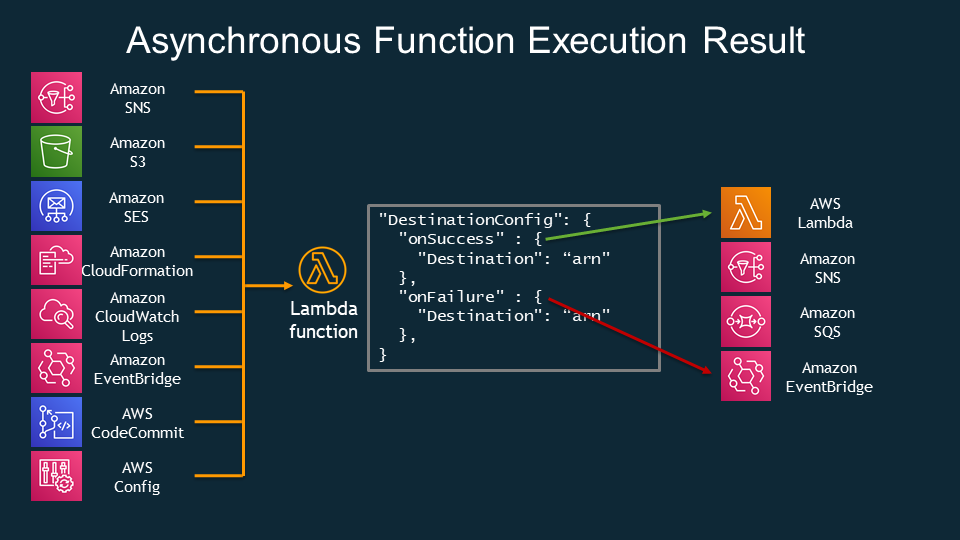
DLQ
- SQS queue
- SNS topic
Cloud Watch Event
Simply Serverless: Use constant values in Cloudwatch event triggered Lambda functions
VPC
How do I give internet access to a Lambda function that's connected to an Amazon VPC?
Read More
- Invoking AWS Lambda functions
- Introducing AWS Lambda Destinations
- https://docs.aws.amazon.com/lambda/latest/dg/with-sqs.html
- Lessons learned from combining SQS and Lambda
S3 and Glacier
S3 Standard-IA and S3 One Zone-IA storage classes are designed for long-lived and infrequently accessed data that still requires millisecond access.
The S3 Glacier and S3 Glacier Deep Archive storage classes are designed for low-cost data archiving. The S3 Glacier and S3 Glacier Deep Archive objects are not available for real-time access. You must first restore the S3 Glacier and S3 Glacier Deep Archive objects before you can access them.
- Glacier archives are encrypted by default, whereas encryption on S3 is an option you need to select.
- Unlike S3’s “human-readable” key names, Glacier archives are given machine-generated IDs.
The biggest difference is the time it takes to retrieve your data. Retrieving the objects from an existing Glacier archive can take a number of hours. You can specify one of the following when initiating a job to retrieve an archive based on your access time and cost requirements:
- Expedited - data accessed using Expedited retrievals are typically made available within 1–5 minutes
- Standard - Standard retrievals typically complete within 3–5 hours.
- Bulk - Bulk retrievals typically complete within 5–12 hours.
Read More
S3 Select & Glacier Select
Amazon S3 Select works on objects stored in CSV, JSON, or Apache Parquet format. It also works with objects that are compressed with GZIP or BZIP2 (for CSV and JSON objects only), and server-side encrypted objects.
Amazon Athena and Amazon Redshift Spectrum also runs SQL queries directly against data at rest in Amazon S3.
S3 Lifycycle
S3 Lifecyle rules consist of 2 types of actions:
- Transition actions - Define when objects transion to another S3 storage class.
- Expiration actions - Define when objects expires. Amazon deletes expired objects on your behalf.
In addition, Amazon S3 supports a bucket lifecycle rule AbortIncompleteMultipartUpload that you can use to direct Amazon S3 to abort incomplete multipart uploads.
Read More
- Managing S3 storage lifeycle
- Configuring a bucket lifecycle policy to abort incomplete multipart uploads
Restore archieved objects.
Archived objects are not accessible in real time. You must first initiate a restore request and then wait until a temporary copy of the object is available for the duration that you specify in the request.
After you receive a temporary copy of the restored object, the object's storage class remains S3 Glacier or S3 Glacier Deep Archive.
You can then create a copy of the restored objects and store in other storage class such as S3 standard storage.
S3 Object Lock
Even with bucket versioning enabled, you are still be able to remove a object version by DELETE object <version>.
With S3 Object Lock, it helps prevent objects from being deleted or overwritten for a fixed amount of time or indefinitely
Read More
S3 Event
Amazon S3 supports the following destinations where it can publish events:
- Amazon SNS
- Amazon SQS
- AWS Lambda
S3 Storage Class
- Minimum 30-Day Storage Charge for S3-Intelligent-Tiering, S3 Standard-IA and S3 One Zone-IA.
- Minimum 90-Day Storage Charge for Glacier
- Minimum 180-Day Storage Charge for Glacier Deep Archieve
- Storage Gateway connects to S3, S3 Glacier and Glacier Deep Archive.
Data Transer cost
- Data transferred out to an Amazon EC2 instance, when the instance is in the same AWS Region as the S3 bucket (including to a different account in the same AWS region).
- Data transferred out to Amazon CloudFront.
S3 Range GET?
Replication & Backups
S3
All S3 storage classes except One Zone-Infrequent Access distribute objects across multiple
availability zones.
You can also enable cross-region replication between a source bucket in one region and destination bucket in another. Note that cross-region replication requires versioning to be enabled on both buckets. Note that cross-region replication does not apply to existing objects. Also, if the source bucket get deleted,the target bucket is NOT deleted. For replicating object deletion, you can enable delete marker replication
In addtion to S3 Intelligent Tier Storage that moves objects that have not been accessed for 30 consecutive days to the infrequent access tier. You can also manually configure lifecycle rules for a bucket that will automatically transition an object’s storage class after a set number of days.
Read more about Replicating objects.
EBS Volume
EBS automatically replicates volumes across multiple availability zones in a region.
You can use Amazon Data Lifecycle Manager to automatically create a snapshot for you at regular intervals. To use the Amazon Data Lifecycle Manager, you create a Snapshot Lifecycle Policy and specify an interval of up to 24 hours, as well as a snapshot creation time. You also must specify the number of automatic snapshots to retain, up to 1,000
snapshots. You can also enable cross-region copy and cross-account sharing.
EFS
EFS filesystems are stored across multiple zones in a region.
To protect against data loss and corruption, you can back up individual files to an S3 bucket or another EFS filesystem in the same region. You can also use the AWS Backup Service to schedule incremental backups of your EFS filesystem
DynamoDB
DynamoDB stores tables across multiple availability zones. To replicate DynamoDB table to different region, you can use DynamoDB global tables.
You can also configure point-in-time recovery to automatically take backups of your DynamoDB tables. Point-in-time recovery lets you restore your DynamoDB tables to any point in time from 35 days until 5 minutes before the current time.
RDS
Multi-AZ Deployments
Multi-AZ deployment provides a standby database instance in a different availibity zone that the primary database instance resides.
RDS synchronously replicates data from the primary to the standby instance. And if the primray instance experiences an outage, it will fail over to the standby instance.
Note that in the multi-AZ deployment, all instances resides in the same region. And the standby instance is not a read replica and cannot serve read traffic. And you can't directly connect to the standby instance. This is only used in the event of a database failover when your primary instance encountered an outage
Read Replica
With Amazon RDS, you can create a read replica of the primary database instance in a different AZ even different region. However, creating a cross-region read replica isn't supported for SQL Server on Amazon RDS.
When creating a read replica, you must enable automatic backups on the source DB instance by setting the backup retention period to a value other than 0.
You can have up to 5 replicas and each read replica will have its own DNS endpoint.
Replicas can be promoted to their own standalone database, but this breaks the replication. Moreover, no automatic failover, if primary database fails you must manually update urls to point at the newly promoted database.
Compare
| Mutil-AZ Deployments | Read Replicas |
|---|---|
| Synchronous replication - highly durable | Asynchronous replication - highly scalable |
| Only database engine on primary instance is active | All read replicas are accessible and can be used for read scaling |
| Automated backups are taken from standby instance | No backups configured by default |
| Always span at least 2 Availability Zones within a single region | Can be within Availability Zone, Cross-AZ, or Cross-Region |
| Database engine version upgrades happen on primary instance | Database engine version upgrade is independent from source instance |
| Automatic failover to standby when a problem is detected | can be manually promoted to a standalone database instance |
Point-in-time recovery
Enabling automatic backups enables point-in-time recovery, which archives database change logs to S3 every 5 minutes.
RDS keeps automated snapshots for a limited period of time and then deletes them. You can choose a retention period between one day and 35 days. The default is seven days. To disable automated snapshots, set the retention period to 0.
Note that disabling automated snapshots immediately deletes all existing automated snapshots and disables point-in-time recovery. Also, if you change the retention period from 0 to any other value, it will trigger an immediate snapshot.
Reference
- Working with read replicas
- Cross-region read replicas
- Read replicas, Mutil-AZ deployments, and multi-region deployments
Aurora
Redshift
Snapshots are point-in-time backups of a cluster. There are two types of snapshots: automated and manual. Amazon Redshift stores these snapshots internally in Amazon S3 by using an encrypted Secure Sockets Layer (SSL) connection.
When automated snapshots are enabled for a cluster, Amazon Redshift periodically takes snapshots of that cluster. By default Amazon Redshift takes a snapshot about every eight hours or following every 5 GB per node of data changes, or whichever comes first.
You can configure Amazon Redshift to automatically copy snapshots (automated or manual) for a cluster to another AWS Region. When a snapshot is created in the cluster's primary AWS Region, it's copied to a secondary AWS Region.
Reference
ElastiCache
A node is the smallest buidling block of an ElastiCache deployment. Each node has its own DNS name and port.
Both Redis and Memcached cluster need to be run in a VPC, a collection of subnets within that VPC.
Redis
A Redis shard is a grouping of one to six related nodes. Redis clusters can have up to 500 shards, with data partitioned across the shards.
Redis Repliation happens in a shard where one of the nodes is the read/write primary node. All the other nodes are read-only replica nodes. Locating read replicas in multiple Availibility Zones improves fault tolerance.
The primary endpoint of a Redis cluster is a DNS name that always resolves to the primary node in the cluster. The primary endpoint is immune to changes to the cluster, such as promoting a read replica to the primary role. Note that Read Replica failover or promotion is happened automatically which is different to RDS (non-Aurora) database.
The reader endpoint of a Redis cluster will evenly split incoming connections to the endpoint between all read replicas in a ElastiCache for Redis cluster.
In addition, you can use global datastores to create cross-region read replica clusters for ElastiCache for Redis to enable low-latency reads and disaster recovery across AWS Regions.
AUTH
Redis AUTH can only be enabled for encryption in-transit enabled ElastiCache for Redis clusters.
Memchached
A Memcached cluster is a logical grouping of one or more ElastiCache nodes. Data is partitioned across the nodes in the Memcached cluster. A Memcached cluster can have up to 300 nodes. And nodes can be run across multiple Availibility Zones.
A Memcached cluster does not have the concept of sharding as Redis. Memcached cluster relies on the client Auto-Discovery to automatically identify all of the nodes in a cached cluster, and to initiate and maitain connetions to all of these nodes.
Comparing between Redis and Memecached
https://aws.amazon.com/elasticache/redis-vs-memcached/
| Memcached | Redis | |
|---|---|---|
| Data Partitioning | Yes | Yes |
| Advanced data structures | - | Yes |
| Multithreaded architecture | Yes | - |
| Snapshots/Backups | - | Yes |
| Replication | - | Yes |
Read More
Security

Data Encryption
Data at Rest
Data stored in Glacier and Storage Gateway are encrypted by default.
RDS
You can only enable encryption for an Amazon RDS DB instance when you create it, not after the DB instance is created.
However, because you can encrypt a copy of an unencrypted snapshot, you can effectively add encryption to an unencrypted DB instance. That is, you can create a snapshot of your DB instance, and then create an encrypted copy of that snapshot. You can then restore a DB instance from the encrypted snapshot, and thus you have an encrypted copy of your original DB instance.
Data in Trasit
- All traffic between AZs is encrypted.
- All cross-Region traffic that uses Amazon
VPC PeeringandTransit Gateway peeringis automatically bulk-encrypted when it exits a Region. - Remote access to your instances using
AWS Systems ManagerSession Manager or the Run Command is encrypted using TLS 1.2. - All data that
Storage Gatewaytransfers to AWS is encrypted in transit and at rest in AWS. - Use the
EFS mount helperto mount a file system so that all NFS traffic is encrypted in transit using Transport Layer Security 1.2 (TLS). - Amazon Certificate Manager (ACM) to generate a TLS certifi- cate and then install it on an
application load balancer,Network load balanceror aCloudFront distribution. AWS Direct Connectdoes not encrypt your traffic that is in transit.AWS Direct Connectand AWS Site-to-Site VPN combination provides an IPsec-encrypted private connection that also reduces network costs, increases bandwidth throughput, and provides a more consistent network experience than internet-based VPN connection- You can use Secure Socket Layer (SSL) or Transport Layer Security (TLS) from your application to encrypt a connection to a DB instance running MySQL, MariaDB, SQL Server, Oracle, or PostgreSQL.
Amazon RDScreates an SSL certificate and installs the certificate on the DB instance when the instance is provisioned. Read more
TLS listener
To use a TLS listener, you must deploy at least one server certificate on your load balancer. The load balancer uses a server certificate to terminate the front-end connection and then to decrypt requests from clients before sending them to the targets.
Elastic Load Balancing uses a TLS negotiation configuration, known as a security policy, to negotiate TLS connections between a client and the load balancer. A security policy is a combination of protocols and ciphers. The protocol establishes a secure connection between a client and a server and ensures that all data passed between the client and your load balancer is private. A cipher is an encryption algorithm that uses encryption keys to create a coded message. Protocols use several ciphers to encrypt data over the internet. During the connection negotiation process, the client and the load balancer present a list of ciphers and protocols that they each support, in order of preference. The first cipher on the server's list that matches any one of the client's ciphers is selected for the secure connection.
Network Load Balancers do not support TLS renegotiation.
Read more about TLS listener for Network Load Balancer
DDoS attack
To protect your system from DDoS attack, you can do the following:
-
Use an Amazon CloudFront service for distributing both static and dynamic content.
-
Use an Application Load Balancer with Auto Scaling groups for your EC2 instances then restrict direct Internet traffic to your Amazon RDS database by deploying to a private subnet.
-
Set up alerts in Amazon CloudWatch to look for high
Network Inand CPU utilization metrics. -
AWS Shield and AWS WAF to fortify your cloud network.
Amazon FSx for Lustre
Amazon FSx also integrates with Amazon S3, making it easy for you to process cloud data sets with the Lustre high-performance file system. When linked to an S3 bucket, an FSx for Lustre file system transparently presents S3 objects as files and allows you to write changed data back to S3.
EFS
- Allows concurrent connections from multiple EC2 instances
- Amazon EFS provides the scale and performance required for big data applications that require high throughput to compute nodes coupled with read-after-write consistency and low-latency file operations.
Performance Mode
- Max I/O Use the Max I/O performance mode if you have a very high requirement of file system operations per second.
- General Purpose General Purpose performance mode has the lower latency of the two performance modes and is suitable if your workload is sensitive to latency. Max I/O performance mode offers a higher number of file system operations per second but has a slightly higher latency per each file system operation.
Aurora
You can invoke a Lambda function from an Amazon Aurora MySQL DB cluster. This approach can be useful when you want to integrate your database running on Aurora MySQL with other AWS services. For example, you might want to send a notification using Amazon Simple Notification Service (Amazon SNS) whenever a row is inserted into a specific table in your database.
To invoke a Lambda, the Aurora DB cluster must:
- Create an IAM role, and attach the IAM polcy for providing permissions that allow Aurora DB cluster to invoke Lambda functions.
- Configure your Aurora MySQL DB cluster to allow outbound connections to Lambda.
Elatic Beanstalk
CloudTrail
By default, CloudTrail event log files are encrypted using Amazon S3 server-side encryption (SSE). You can also choose to encrypt your log files with an AWS Key Management Service (AWS KMS) key.
For global services such as AWS Identity and Access Management (IAM), AWS STS, and Amazon CloudFront, events are delivered to any trail that includes global services.
To avoid receiving duplicate global service events,
- If you have multiple single region trails, consider configuring your trails so that global service events are delivered in only one of the trails.
Data Event
You can currently log data events on different resource types such as Amazon S3 object-level API activity (e.g. GetObject, DeleteObject, and PutObject API operations), AWS Lambda function execution activity (the Invoke API), DynamoDB Item actions, and many more.
Read More:
AWS Trusted Advisor
-
S3 Versioning
-
Redshift Clusters
-
Exposed Access Keys
-
Reserved EC2 Instance
-
Service Limit
Cost
The main distinction between RIs and Savings Plans is the former commits to number of instances used (RIs), while the latter commits to a minimum dollar per hour spend (Savings Plans).
Reserved Instance
- Standard Reserved Instance, enables modify AZ, scope, networking type and instance size.
- Convertable Reserved Instance, enables modify instance family, operating system and tenancy.
You can also go to the AWS Reserved Instance Marketplace and sell the Reserved instances.
Scheduled Reserved Instance
Spot Instance
Spot Instance runs whenever capacity is available and the maximum price per hour for your request exceeds the Spot price. Spot Instances are a cost-effective choice if you can be flexible about when your applications run and if your applications can be interrupted
Saving Plan
- Compute Saving Plans, reduce costs of EC2 Instance usage by up to 66%, regardless of
instance family,region, size, AZ, OS or tenancy, EC2 Intance usage even includes ECS and Lambda. - EC2 Instance Saving Plans, reduce costs of EC2 Instance usage by up to 72%, regardless of instance size, AZ, OS or tenancy
Read more
- Saving Plans FAQ
- AWS Savings Plans: What They Are And Why You Should Care
- https://aws.amazon.com/blogs/aws/new-savings-plans-for-aws-compute-services/
- Using Sport instances
SNS
Designing durable serverless apps with DLQs for Amazon SNS, Amazon SQS, AWS Lambda
Cloud Watch
- EC2
- CPUUtilization, DisReadOps, DiskWriteOps, NetworkIn/Out
- Detailed monitoring is 1 minutes, Basic monitoring is 5 minute peroids.
- RDS
- CPUUtilization, FreeableMemory, Database connections, Read/WriteLatency
- Enhanced RDS
- RDS processes, RDS child processes, OS processes
- ECS
- CPUUtiliation/Reservation, MemoryUtilization/Reservation
- Cloud Agent
- can be intalled on both Linux and Windows instances
Kineise
Kineise Data Stream

AWS Application Auto Scaling
Kineise Firehose
Destinations:
- S3,
- Redshift
- Amazon Elastic Search
- Http endpoint owned by you
- Thirdparty providers, including Datadog,New Relic and Splunk
AWS Backup

Others
- Cloud Search
- AWS Step Functions
- serverless orchestration for modern applications.
- ACM and IAM certificate store
- import third-party certificat
- Direct Connect
- AWS Batch
- AWS KMS
- Disaster Recovery
- CloudFormation
CreationPolicyandcfn-signalfor associate resources.updatePolicyis primarily used for updating resources and for stack update rollback operations.
- AWS CloudHSM
- Amazon Polly
- Amazon EMR